Blog

Weekly Update: 9 Apr 2022

This week was again spent trying to get the ray tracer validated, and I think I am victorious, but that’s always subject to further revisions! Well, not all ray tracer stuff. I worked on the corporate taxes for SR&ED which is a super program for research companies like Sun Aquasystems. Any Canadian corporation should check it out.

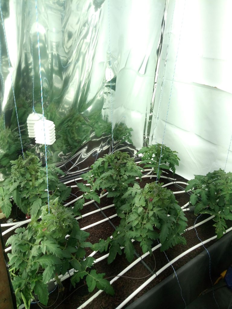
I also worked on the modelica simulation of the growth chamber. Because the scanning of the plants didn’t work out it’s very difficult to make an accurate judgment of LAI, which means it’s very hard to calculate leaf temperature, which is key. The moral of the story is you should just measure leaf temperature with a thermocouple, which I will do in the next trial. I think I will devote my time to making a good simulation of the test greenhouse, which will then inform what measurements I should take for validation. A major complication that I have is that the greenhouse is relatively shallow so all the thermal radiation calculations need to look at the south wall and the roof and north wall, while vanthoor could consider it as one dimensional towards the roof. I may have to use the ray tracer to calculate view factors.

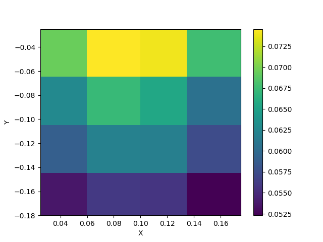
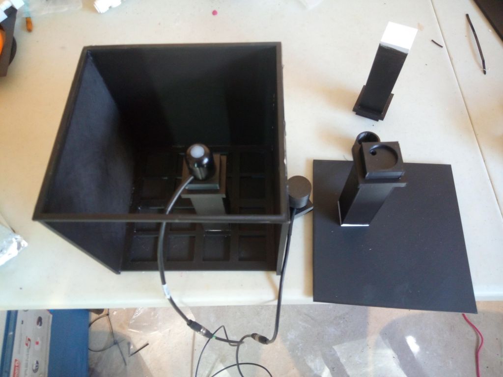
For the ray tracer I tried validating it outside with 0,1,2 layers of greenhouse glazing. First I found the sensors did not read the same after rotating 90 degrees, and after testing with a different stand, I think it was a problem with the side shade. So I took that off, accepting that there would be some error from that. I also raised the sensors so that the albedo of the text box should have no effect, and I waited for a cloudy day so I only had to deal with diffuse light, and… finally the measurements seem pretty reasonable. I got 83% transmission of diffuse light through 1 glazing layer and 71% through two layers. If the index of refraction is 1.55, then 83% transmission is exactly correct. 0.83^2 is 0.69, but there is multiple reflection paths so 71% is reasonable.

After much calculating, the rayctracer simulation gave: 0.827 and 0.716. This was done by simulating the sun at 15 different zenith angles and all around the compass rose the summing the results. Note that this is not the same as putting the sun directly overhead and then through a perfectly diffusing sheet. Only took me a day to realized that… Oh well. At any rater, I think that’s pretty conclusive that rayctracer gives valid results, at least for glazing transmission.

I think the next step is to make some small greenhouse panels with a PAR sensor in each, and log data for a day, comparing with a solcast-rayctracer simulation. That will give me information about how accurate I can expect the historical simulations to be and perhaps expose any problems in rayctracer. But I haven’t had to correct the tracing code so far so that’s good.

Weekly update: 2 April 2022

I measured LAI (leaf area index) by hand, using the method of Carmassi 2007. My first attempts were not very accurate/reproducible, but I was eventually able to get reproducible results by carefully measuring out from both sides of the leaf stem separately. My leaflets often grew off at angles, but I measured along the center line of each. I will have to validate this method destructively at the end of the experiment by pressing the leaves flat and scanning them for area, but it seems doable this way even if I have to re-calibrate the model for this cultivar. The amount of reaching around and pushing other leaves out of the way makes me very pessimistic about the hope of any 3D scanning process working. It takes about 15-20 min per plant to measure LAI using this method, which is not extreme and probably less than it would take for a good 3d scan, so this is the way forward.

I promised new calibrations of the ray tracing last week and I have failed. Well, sort of. It took me a long time to figure out that my new spot light source is not completely stable! Light output is +/- 2% over a 30 min interval, seemingly at random. I think I just have to accept that level of inaccuracy because I’ve spent far too long trying to calibrate as is. I measured the transmission of the glazing that I’m currently using on the greenhouse, and got 93.39% transmission of diffuse light, which is pretty high. Of course, that could be partly the light’s fault.

The analytical calculation from Fresnel equations gives, for index of refraction of 1.5, 0.84% transmission. The data sheet for this film claims 90% transmission, but that’s usually direct normal light, since that’s the best possible situation and marketing people like to report high transmission values. My simulation reported 86.7% std=0.5%. So what’s happening?

First, it’s tempting to think of doing two experiments with and without the greenhouse film as measuring the transmission, but this is not quite true. The side shade on my sensor means I’m not measuring exactly diffuse light, but a subspace of directions that is weighted toward the normal direction. So measuring a transmission higher than pure fresnel equations for diffuse light is to be expected, but not higher than the fresnel equations for direct light.

The other problem that I think is present is that when a ray is emitted from my diffuser, which is simply baker’s parchment paper, it may hit the film and reflect back to the diffuser. But the diffuser is white with high albedo so that ray is more likely than not re-reflected back towards the greenhouse film at a different angle. This albedo of diffuser effect is not taken into account by my simulation.

So I have two choices, measure the albedo of parchment paper and include that in the simulation, or revise my light source to avoid this problem. I haven’t decided yet.

While I was waiting on the sensors I also went back to compare my modelica greenhouse simulation with that of the thesis Vanthoor 2011. I actually wrote my simulation without looking at his because I wanted it to be completely independent and… Just kidding. I just didn’t see that he had all the details in an appendix until I had finished mine. So that was kind of a waste of my time, but I did do something better I think and left out some complications that he has and I don’t need. However, now going back I was able to fix some stuff I wrote and most of all use his calibration values for crop transpiration. I was hoping to be able to simulate my growth chamber, but I’m not sure that’s possible this far in. I don’t have records plant height, the LAI (leaf area index), nor any measurement for K in the canopy absorption. I could just use vanthoor’s estimate for K, but not having the LAI and height of the plants makes it hard. Perhaps it can still be done though and it’s probably good preparation for the full model validation to try.

Weekly update: 21 Mar 2022

This week was spent debugging the ray tracer, and adding the functions I need for simulating actual greenhouses. I did find a bug in the data saving function, so I have to redo the calibration. I don’t think it was that serious in these cases, since it agreed well with experiment, but better safe than sorry. I also ordered a spot light to provide intense even illumination for the experiments as I think the even illumination was the accuracy limiting variable. I tried jerry rigging my current lamp with reflectors etc but couldn’t get totally even illumination. When that arrives I can make some more heat maps that should be even closer to the simulation.

I now have code that can take a greenhouse model, ray trace all of the possible sun directions, and then save those results to file. Another program can take solcast like data of sun azimuth, sun zenith, direct sun flux, diffuse sun flux and compute quickly (1 sec) what the flux will be on every facet of the greenhouse. I also provide an estimate of the accuracy, which even for a quick test was generally good, about 1% error. This way I can simulate the greenhouse illumination over years of data quickly without having to ray trace separately for each day’s weather conditions.

For simulation, one of the remaining questions is how much light the plants absorb. I was trying to measure this with 3d scanning, but I just don’t have the budget for the quality of 3D scanner that could make that work. If anyone is interested in a lightly used revopoint 3D scanner let me know… I’ll sell it at half price.

Anyhow, Vanthoor assumed the plants were a block of green tinted glass and the darkness of the tint was related to LAI, or leaf area : floor area ratio. And then a correction factor in there of K=0.7. That’s a good start and a block of glass is definitely easy to do in the ray tracer, but I somehow doubt that 0.7 factor is constant under all conditions. I would like to directly measure the absorption, and measure K for myself. PAR sensors are pricey but I think I might be able to get by with 2$ lux sensors, which would mean lots of sensors for easy fitting to ray tracer data. I’m not sure I’ll pursue this immediately, but it’s on the todo list. My K might be also different depending on sun angle since all previous measurements have neglected the south wall effect.

Weekly update: 18 Mar 2022

This week was spent validating the ray tracer. I used the 3D printed box and tested and… the simulation was different from the measurements. Narrowing down the source of this was difficult, but the final suspects were the grazing angle response of the apogee sq-120 sensor and the quality of my diffuse light.

I made 3 different diffuse light sources, but the only one that seemed to work was this:

A SAD lamp suspended over a sheet of glass. On the bottom of the glass, stretched taught was a piece of bakers parchment paper for diffusing.

The sensor response was also tricky. Apogee has this nice plot of their sensors vs sun angle but the low angle error goes off the scale. This is probably because at dusk the light is mostly diffuse. But they do state that 45 degrees or less it’s +/- 2%.

I’m ok with 2%, so I 3D printed a tiny ring to fit exactly over the sensor window and block light coming in from grazing angles which you can see in the picture of the box above. The sensor window is 11mm in diameter, so I made the shade 5.5mm tall. I painted it black and tried again. Of course I also had to include the ring or “sideshade” as I named it in the rayctracer simulation but that’s easy enough to do since I already had it in CAD.

I repeated the measurements and simulations and made a heat map based on the intensity of light at the 16 sensor locations in my box. I normalized all plots to have sum of all tiles equal to one.

It’s not quite perfect, but a paired t-test between the simulations and measurements revealed no statistically significant difference. I think the quality of my diffuser is what’s holding me back. The final validation for next week is to compare measurement and simulation of transmission through a piece of greenhouse plastic. If that passes, I will have great confidence in the rayctracer simulations for a full greenhouse.

These sort of test passing I always view as a bit of a minor miracle. I know it should work, ray tracing is a proven concept, and I tested the code as I developed it, but the real world has so many uncontrolled variables. What if I hadn’t thought of the idea of a sideshade? Would I just be stuck or have given up? It all looks well though so praise the Lord!

Weekly update: 11 Mar 2022

I apologize for the lack of an update last week, I took the week off due to a family illness. So no work done means no update either!

This week I’ve been working on validation of the ray tracing model. I though I’d found another forward ray tracing code that I could use to at least validate mine, solstice, but in the end I’m not sure it’s worth it. Kudos to the developers of solstice at making it easy to install, see my post on how to do that, but massaging the output data into a form I can use takes a long time. Then making sure my scene objects are setup correctly and comparing with my ray tracer… not sure that it’s worth it. I also tried soltrace and it kept crashing so I gave up on trying to validate with that too.

What I did do was go back and carefully redo all the internal rayctracer tests (my ray tracer is called rayctracer because it traces rays and is written in c++. It is not racy but maybe that helps remember it’s name). Once these were good, I made a box in CAD and 3D printed it.

CAD model of ray tracing test box
A few rays traced and plotted. Assuming a diffuse light source on the top of the box and low wall albedo
The real thing. The holes in the bottom allow me to pop in the sensors in different locations.

I made a diffuse light source with some 100% diffusing greenhouse plastic and some LED strips that sits perfectly on top of this box. By exporting the files to .stl, I can run a simulation of the rays in that box and also measure the real light flux in the box with PAR sensors. I feel like this is the only way I’ll really be able to trust that my rayctracer code is accurate enough.

There are a bunch of complications to doing this in real life. First, the PAR sensor isn’t perfect and grazing angle rays aren’t picked up as well. I’ll have to correct for that in the simulation. Second, the albedo of the inside of the box is unknown. I painted it black so I know it’s low, but that will have be be a fitting parameter. This actual test will be next week’s task.

The growth chamber tomatoes continue to grow despite my watering problems. Leaf angle continues to be oriented towards the south wall and the southmost plants have less leaf area than others, which makes sense they don’t need it. They also seem to have larger fruits, but I’ll have to wait until harvesting to measure that.

Weekly update: 25 Feb 2022

This week was spent primarily on trying to design the insulation for the glazing during the night.

The guiding principles here is cost. Insulation, especially exotic forms, can be very expensive. The greenhouse insulation needs to be very thick, and cover a large area, so cost is the primary criteria. This limits the options to: Cellulose loose fill, recycled EPS styrofoam, and aluminized plastic radiant barriers. I’ll present here the steps I took in chronological order.

1) eversion is the process of growing by unfolding from inside itself. This is easy to do with small amount of pressure. I can fill a tube that grows down a test channel similar to what we’d have in greenhouse glazing. I built a test rig and it worked just fine. See video below for nice footage of a thin tube eversing, much better than what I could film. Mine did have a string down the center so I could wind it back up (deversion?) when the sun comes up.

2) fill eversion channel with cellulose for insulation? This is hard. The cellulose does not flow at all, binds up on itself. Also filling is tricky if the tube is long. Cannot everse when full of cellulose, because it does not flow.

double ended eversion to contain the dusty cellulose

3) Fill eversion tube with EPS beads. Bead fill greenhouse windows have been done before, this eversion step would eliminate problems with the glazing becoming clouded with dust and static clinging beads. But to test further I need to make a grinder for EPS. EPS is commonly landfilled so it should be free, but you have to source it and grind it yourself. It doesn’t make any sense to ship it any great distance since it’s so fluffy.

There will also need to be a very large storage container for the EPS when insulation is not deployed, and could be a disaster if it rips open, beads everywhere.

4) The eversion tube could have little fingers on it pointing in. These could fluff up the cellulose or EPS as it retracted to avoid the compression problems. I have my doubts as to this actually working, but when retracting the inside centre is moving twice as fast as the tip, so this speed differential might help. I have yet to try this.

5) The eversion tube could be square with pockets of insulation built into the sidewalls. Then it could be retracted and expanded pulling the insulation along with it. Insulation would probably need to be incompressibleish, so EPS / cellulose mix or similar. Cellulose packs down an is not elastic, EPS beads are pretty well incompressible at low pressure and elastic. Where to store it when sun is out may be a problem, it won’t be as easy to turn as other eversion tubes but probably could still wrap around to north side of structure or storage tubes on the ground. It’s possible that it could be entirely air powered by pressure differences in the glazing and storage area.

6) A long polyethylene sock of insulation might be able to just slide into place without eversion. The sliding doesn’t seem to damage polyethylene’s optical qualities. Greasing it with glycerin/water mixture (n= 1.33 to n=1.47) may add a bit of anti reflection coating on the glazing which would help light transmission in general. The problem is storage when glazing is open, greenhouse has to be twice as long east-west since these socks will not be able to go around corners. This is probably the simplest idea likely what I will do on the test greenhouse just to demonstrate the insulation idea works.

7) The eversion tube could be made of reflective plastic, with many interior layers. Then it acts like a GFP (gas filled panel) that deploys through air pressure, retracts with rope. The problem here is manufacturing even a test tube is very difficult, and it’s unknown how many cycles the aluminized plastic film would last before all the coating breaks off. The great advantage here is that at scale it could be quite cheap and there is no insulation storage problem. I tested one with 2 inner layers, aka a divider down the middle and it seems ok. Retracting it wants to buckle probably because the pull force is off centre, but in a contained channel that’s still ok. On a larger number of layers in an eversion tube, the pull channel should be the central one.

8) Other ideas are just a big blanket filled with EPS and cellulose that you can pull over the greenhouse at night. This gets into complications with high winds and snow, but this is generally how it’s done in northern Chinese passive solar greenhouses. The blanket then has to roll up, or at least reasonably flexible. In some cases it’s segmented so each part can be rolled by hand. This is sort of a back up plan. I think this would cause lots of problems in the wind (100kph wind here is relatively common) so I’m looking at a way to keep the insulation inside the double layer for now.

Weekly update: 19 Feb 2022

This week I finished the modelica simulation for tomato yield. It seems to give reasonable results with the calibration parameters used by B H E vanthoors, but I have not yet built up a simulation for my growth chamber to calibrate it against that. The main difficult variable is determining how much light is absorbed by the tomato plants, hence the other project of scanning the tomato plants and ray tracing.

Unfortunately, the tomatoes are now so large that I cannot get the scanner in around them. When I planned the experiment I did not realize how far back the scanner needed to be, nor how wide the plants would get. They have pretty well covered all the floor area of the growth chamber now. Fortunately, it’s pretty obvious that the plants adapt their leaf angle according to the available light. Cultivar is Maxxis from axia seeds. The plants along the south wall have leaves that are almost vertical on the south side, and then almost perfectly horizontal on the north side. These are also the plants that have the most immature tomatoes. So while not as quantitative as I was aiming for, it does look like tomatoes can use light coming from the side just fine.

I measured the albedo outside my greenhouse, which was low, 0.2 – 0.4 depending on snow cover. It will be interesting to see the how much light can be added by adjusting the albedo in the ray tracing simulation. I realized that I can validate my ray tracer against the solTrace program, which is a similar solar power ray tracer. I initially was going to use solTrace instead of my own program, but it was so difficult to build depending on many libraries and with a complicated GUI that I gave up and made my own. My program uses only header files and has command line interface only. So I will aim to get some of this validation done next week.

The rest of this week was spent trying to sort out the night time insulation. I feel like that’s best explained in pictures so I’ll wait til next week when the testing rigs are complete. Everything looks plausible for next winter though, so the tentative plan is to plant in the test greenhouse July 2022 for harvest through next fall, winter, and spring. I was adding plywood panels to the test greenhouse this week and insulating the soil between the greenhouse part and storage section. The non-glazed greenhouse walls will be insulated with blown in fiberglass or cellulose to R-40 so the heat loss there is minimal.

Weekly update: 11 feb 2022

The growth chamber soil has still been giving me problems. On monday, the leaves were curling and I had pock marks on the leaves. I think it was likely Oedema, where there is too much water. Combined with this the air exchanger in the lab had broken so humidity was slightly higher than normal 60%-70% instead of 50%.

I fixed the air exchanger and held off on watering for 2 days until the water tension went up to 30kPa. Most of the leaves recovered, and I got some of the first fruit buds forming. I think I had been over watering, which may also have been the problem with the nutrient deficiency. Too much water means not enough root development. After all this I found a guide to hydroponic irrigation timing for commercial tomatoes and they generally use the EC (electrical conductivity) of the nutrient run off to guide timing. They also allow for a drying down at night to promote root development. Unwittingly, I may have done the right thing by withholding water as often high EC and dry conditions are used to push the plants into a generative fruit producing state in plants about the size mine are currently.

Ultimately though, soil is bad choice for validation as the correct water tension at each stage is another unknown variable. I’ll run the current experiment until I get some ripe fruit and compare to B H E Vanthoor’s model, but I doubt the yield will be as high as the model given all the non-optimal fertilizer and watering issues. For the next experiment I’ll change to hydroponic substrate, even if that’s not the end goal and also allow for each plant to be removed from the growth chamber individually for bettering scanning.

I worked on implementing Vanthoor’s tomato yield model in Modelica. The greenhouses-Library for Modelica had already done this but… That model would not compile. I fixed it so it would compile and it always gave zero yield. So I started fresh and wrote my own implementation, dividing the plant into sections and testing the leaves, stem, buffer, etc individually. I found the error, there was a typo in Vanthoor’s manuscript. It was correct in the paper he cited though, so I got that part working. I still need to put in the details for fruit development, but I should have it working by next week.

How to fertilize organic plants cheaply and completely

My experience this week raises an interesting question though: If watering with what was really just a bit diluted fertilizer on soil composed of pure compost caused nutrient deficiency, how are you supposed to grow organic tomatoes? My situation is a little unique, there is plenty of light, temperature and humidity are always optimal, the plants need a lot of nutrients because they are growing fast. But fast growth is desirable, and it seems the the nutrients in the compost (1.8% phosphorus by dry weight, I have the compost analysis report) are poorly soluble. This means you either need to add tons of water to leach them out and lots get wasted, or you need a more highly soluble nutrient source.

I propose an organic farm two nutrient loop for nitrogen and phosphorus. Nutrients are continually exported from the farm in the crop biomass, so these must be replaced.

Municipal compost, food scraps, manure can all be imported and processed in an anaerobic digester. The nitrogen is in a highly soluble form of ammonia in the liquid portion of the digester effluent. It’s also sterile and can be used as a liquid fertilizer. The solids will contain some nitrogen, but also cellulose which can not be easily broken down in anaerobic digestion, and phosphorus which is generally not as soluble. Methane bio-gas is produced as well which can be captured for fuel.

Wood waste, construction and demolition waste of wood and drywall can also be imported at low to no cost. In fact, construction waste disposal is an additional income stream. These contain phosphorous, calcium, sulfur, and cellulose but very little nitrogen. These can be pyrolyzed, along with the digestor solids to produce biochar and heat. The biochar will have very little nitrogen, but the other nutrients should be converted into a more soluble form.

By using these two waste streams, the farm has a supply of high nitrogen liquid fertilizer, and by leaching the biochar, a high phosphorous liquid fertilizer. The concentration of both will fluctuate depending on input streams, but the rate of application can be adjusted daily to avoid nutrient deficiency after measuring leaf phosphorous and nitrogen levels with a portable spectrometer.

The entire process is somewhat capital intensive, space for accepting waste is needed along with an anaerobic digestor and pyrolyzation furnace, and associated plumbing for collecting and distributing the resultant fertilizer. However, it also provides free heat, or heat and electricity with a generator, and is carbon emission negative if the biochar is returned to the soil. In some possible future, carbon capture credits may be valuable, but biochar is excellent for the soil fertility regardless.

This is not something we’re actively pursing at the moment. Greenhouse design is the current priority, but this system could fit in well with a solar greenhouse, even reducing the need for heavy insulation by using the waste heat.

Weekly update: Feb 4 2020

The big question this week was why are the tomato leaves turning purple on the underside? I think the answer was/is phosphorous deficiency which was very surprising. I’m growing in pure compost, watered with hydroponic tomato fertilizer. How could there possibly be lacking nutrients?

The first part of the equation is: Bacterial or algal growth in the fertilizer reservoirs. I had this problem before in an algae experiment, where after mixing F2 algal fertilizer a bunch of sedimentation happened. I fixed that by using two peristaltic pumps to add part A and part B separately, each part along being insufficient for growth. I don’t have that option here because the two parts of this solution have all the necessary nutrients alone, and I had a separate reservoir for each plant. The bacteria also had made clogs in the dripper hose so not all the drippers were working.

I needed to fix the problem asap, so sadly now I will not be able to measure the amount of water used by each plant. I took apart all the blumats and drippers, washed them in bleach solution. I then used new (opaque) hose and set up one dripper per plant. I am now mixing a new bucket of fertilizer each morning, and pumping it directly onto the plants over the course of an hour. There is lots of runoff, but I siphon that out of the sump. I’m using 3 liters for the 6 plants right now. Near the southmost plant the tensiometer read about 2 kPa while watering, and about 10 kPa right before the watering starts the next day. I may switch to a gravity feed since that will lower the flow rate, and allow for better soil absorption. I purge the lines with water after each fertilizer dose.

So far, this seems to be working. Purple color is receding and lots of new growth without purple. Generally quite a bit of runoff, 2.6 l recovered out of 3 l added today. But I think the experiment can still continue. Or “trial” sorry, this technically isn’t an experiment because I don’t have a error analysis / statistical test setup before hand. I want to compare with the mathematical tomato yield model, and get some good plant scans to see how tomatoes capture light from the side.

I also put a new cover on the trial greenhouse with inflated double wall. That was the first time I’d done a double layer, and I think it went ok. Hard to get it tight, as usual, and the cold weather doesn’t help. Our ultimate goal is to make an inflatable greenhouse cover where you can just unroll and inflate. I now think that’d be a pretty easy sell to anyone who’s had to mess with installing a traditional double layer. I have the PAR sensors setup inside and out collecting data to use with the ray tracing validation.

If anyone reading this knows of an importer of PATI lux greenhouse plastic in Canada or USA, let me know! I settled for MUTI this time and I can see that it’s not nearly as good. Diffusion is too high for my purposes.

Plant scanning is coming along ok, I may run into trouble where I cannot move the scanner around the plants well because there is not enough clearance between plants. Were I to repeat, I’d have each plant in a movable pot so I could take them in and out of the growth chamber. The orientation rig works, but I’ve found a ribbon of magenta on the soil surface works